Time Synchronization for the CBP Calibration System#
Abstract
Description of the time synchronization protocol for the Collimated Beam Projector (CBP) calibration system.
Introduction#
The Collimated Beam Projector (CBP) will be used to measure the wavelength-dependent throughput of the Simonyi telescope. The CBP, mounted on the dome, will project collimated bursts of monochromatic light into the telescope. If we know the intensity of the bursts then we can calculate the telescope throughput. To measure the burst intensity, we calibrate a photodiode on the integrating sphere at the input to the CBP relative to an external detector, thus measuring the CBP transmission. The external detector is known as the CBP Calibration System. To calibrate the CBP at the milli-mag level, as is our goal, it is critical that we know the time that laser bursts are sent relative to when measurements are taken with the detector/photodiode to a very high, millisecond level accuracy. The Rubin network will use NTP, not PTP, and thus will not reach millisecond precision. This tech note discusses the method, hardware, and software proposed to achieve the requisite timing precision.
Details of the time synchronization problem#
Setup#
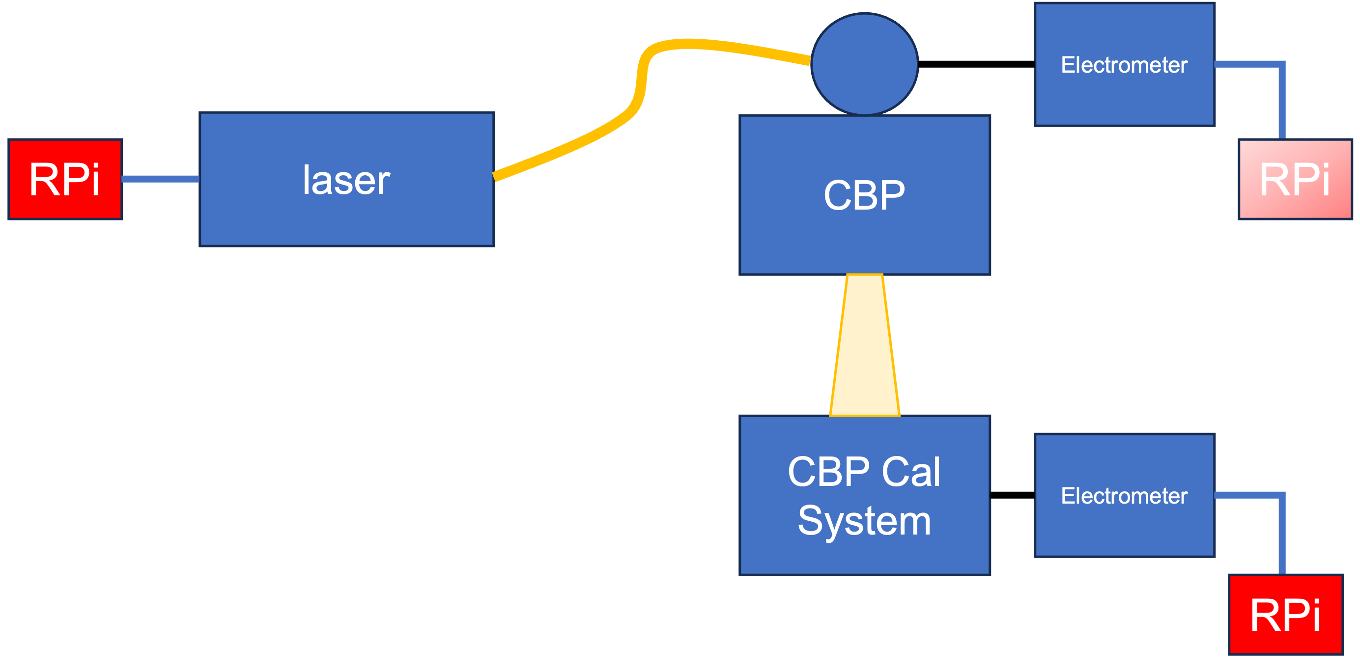
The integrating sphere mounted at the input to the CBP has three ports. The first takes the laser fiber as the monochromatic light source, the second is the output port to the CBP, and the third holds a NIST calibrated photodiode which we use to measure the laser intensity. This photodiode is read out by a Keysight electrometer. The CBP is then aligned with the CBP calibration system, which contains a large lens that focuses the incident beam onto a photodiode. This photodiode is also read out by a Keysight electrometer. The goal is to record the exact moment that laser bursts are sent and measurements are taken with the electrometers so the data can be aligned.
Data Acquisition and Synchronization#
At each wavelength we output a series of laser bursts and both electrometers read out time traces of the charge accumulated from the photodiode over these bursts. From this data, we can subtract off the background charge accumulation and determine the total amount of charge accumulated due to the laser bursts. At wavelengths where there is a large signal, we can directly fit the data traces, but for laser wavelengths with smaller signals, determining the start and end of each burst through fitting these data traces alone is challenging. We solve this problem by syncing the measurement times to the laser burst times. The electrometers output a TTL signal at the start and end of each data trace, and the laser outputs a TTL signal for every laser pulse. At LPNHE, the team uses a logic timer, created by Marc Betoule, to sync up the start and end of the electrometer traces along with the laser bursts to sub-millisecond precision by connecting the TTL signals via BNC to the logic timer.

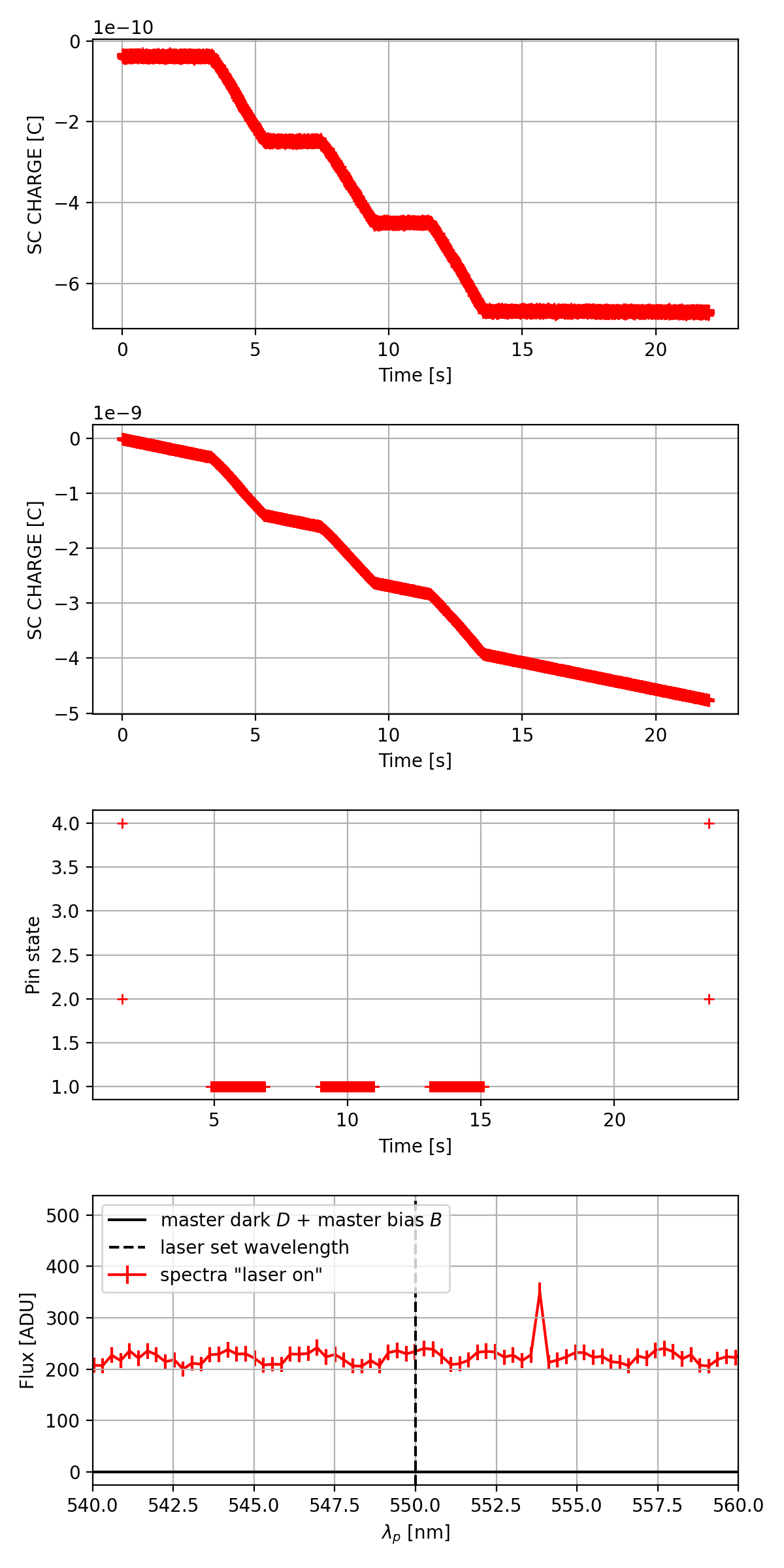
Fig. 1 From top, (a) Data trace of the charge from the Rubin CBP photodiode at 450 nm, measured by the Keysight electrometer. (b) Keysight electrometer charge readout trace for the calibration photodiode at 450 nm. (c) Pin states read out by the logic timer. Pin 1 is the laser TTL signal and the pin detects pulses in a burst. Pins 2 and 4 are for the CBP and CBP calibration photodiode electrometers, respectively. (d) Spectrograph signal.#
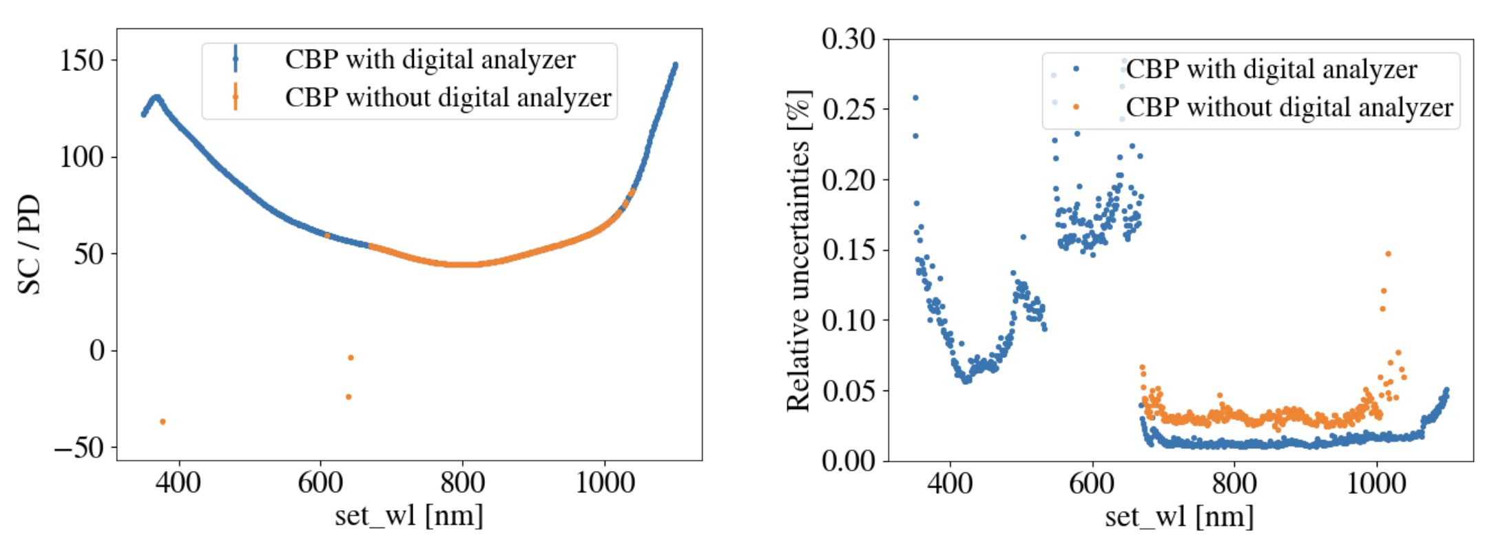
Some wavelengths have a strong enough signal that the logic timer is not needed to find the start and end of each burst. However, some of the wavelengths have a weak enough signal that the fit fails without the logic timer. Jérémy Neveu provides the following analysis of the data at LPNHE with and without the logic timer (here the CBP calibration hardware used a solar cell, not a photodiode):

Fig. 2 Left image: The ratio of the solar cell charge to the photodiode charge with fits done with and without the logic timer (or digital analyzer as it is sometimes called). Right image: percent uncertainties in the fits with and without the logic timer.#
In the range of ~700 to 1000 nm, the fits work well without a logic timer. However, outside of that wavelength range, the fits fail. Thus, the logic timer is necessary.
Time Synchronization Plan for Rubin#
The logic timer allows for both a rescaling of internal clocks of the electrometers relative to each other and the laser and for finding the correct timing offsets. Thus we can know the exact start and end of each burst in each data trace, allowing for a more precise determination of the charge accumulated for each burst.
Implementing the logic timer as described above will not work on the Simonyi telescope due to the fact that the CBP calibration system will be located on the TMA and the CBP will be mounted on the dome. A physical connection via cable is not viable, hence, we are suggesting a comparable option.
Without the logic timer, the data can only be analyzed in the wavelength range of ~669 to 1050 nm. However, within that range the uncertainties still tend to be well under a tenth of a percent. We intend to use these high SNR wavelengths to calibrate the clocks of two or three local Raspberry Pis and to find the time rescaling factor of the electrometers. Jérémy Neveu and others have found that the internal clock rescaling is stable over multiple weeks to within one part in \(10^{-4}\).
Operation#
Have one Rasberry Pi linked to the laser TTL output and one linked to the CBP calibration electrometer TTL output (and perhaps also one linked to the CBP electrometer TTL output).
Run a CBP transmission calibration sequence (where data is taken for a series of laser bursts at each wavelength over a range of wavelengths). For each measurement trace, have the local Raspberry Pis record the times of each laser pulse and of the start and end of each electrometer trace. Make sure that sequences with a high SNR are interspersed throughout the scan.
Fit the data traces for the high SNR wavelengths and find the start and end times of each burst. Use that to find out the timing offsets for the internal clocks of the Raspberry Pis and the rescaling factor between the electrometer clocks and the laser clock.
Use the calibrated Raspberry Pi clocks to synchronize the traces and find the start and end of each burst for the low SNR wavelengths.
Hardware#
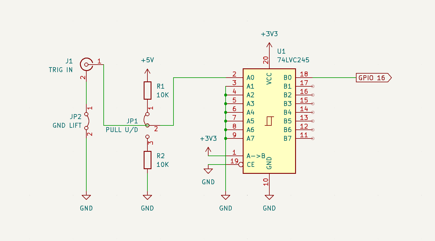
The logic timer will be implemented using Raspberry Pis (4b) with the adafruit ultimate GPS hat. Additionally, all RPis will have a 73LVC245 level-shifter chip and an input connector on the adafruit hat to accomodate the TTL input. The RPis will be located in the electronics cabinets near the laser and the CBP calibration system. They will read out TTL signals from the laser and the electrometer, respectively.

At this time it is planned to add a RPi for the laser and the CBP Calibration System. We may want to add one to the CBP in the future.

Fig. 3 In this functional diagram, light travels from the laser to an integrating sphere via optical fiber. The light is then sent in a collimated beam from the CBP to the CBP Calibration System. The charge in the photodiodes at the CBP and CBP Calibration system are read out with Electrometers (black lines). When a pulse is sent by the laser, it sends a TTL signal to the RPi. Similarly, when an exposure is taken with an Electrometer, a TTL signal is sent to the RPi (blue lines)#
Note
Previously, we were using the Keithley electrometer to measure the photodiode charge. The Keithley does not output a TTL signal with measurements. We are now using the Keysight electrometer for several reasons, one being that it does have a TTL signal output.
Software#
For the following discussion, the term measurement refers to a series of bursts at a single wavelength sent from the CBP (via laser) to the CBP Calibration System. Each time a measurement is made, we want to record the signals from the laser and the the electrometer(s) in a way that can later be identified with the measurement. A python progrm running on the Raspberry Pis needs to be run for each of these measurements. We need a way to run that program asynchronysly with a measurement. For reference, the laser and electrometer measurements will be run with a asynch gather.
await asyncio.gather(laser.cmd_triggerBurst.start(),
                     electrometer.cmd_startScanDt.set_start(scanDuration=1))
For the laser, a TTL signal is sent for every pulse. The number of pulses depend on the size of the burst, but they will always come at 1kHz. This is too much data to be saved directly to the EFD, so it would be best to save the output from the laser in a file on the lfa, with the filename recorded to the EFD.
For the electrometers, a TTL signal is sent at the start and end of an exposure. Since this is low enough latency that the timestamps recorded by the RaspberryPi can be logged as messages in the Electrometer EFD when they occur.
The analysis software used to combine the timing data with the electrometer data was written by the STARDice group at LPNHE. This will need to be modified for the exact data products supplied, but the main structure already exists. This software will be saved at <https://github.com/lsst-ts/cbp_analysis>.
Tests and items we still need to do#
Confirm that the Raspberry Pi clocks remain in relative sync for a sufficiently long time such that we don’t have to repeat the measurement too frequently. Bench tests are being done for that.
Add the Raspberry Pis to our hardware setup.
Incorporate the Raspberry Pis into our data taking scheme.
Write analysis code for the Raspberry Pis.